We describe below the main properties which characterize microfluidics systems: dimensionless Reynolds number, Capillary number and Peclet number. They compare viscous, inertial, interfacial forces, advective and diffusive forces, and determine which contribution dominates over the others. At this range, physics laws are differently appreciated than in the macroscopic scale.
Reynolds number: Viscous vs. Inertial forces
First of all, the inertial and viscous forces are compared in the dimensionless Reynolds number Re. It is expressed as:
Re = 𝜌νL/µ
where 𝜌 is the density of the fluid, ν the velocity, L the length of the system, and μ the dynamic viscosity.
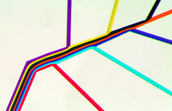
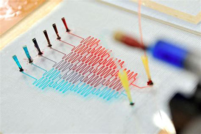
Figure 1: Laminar flow into microfluidic channels [1].
Based on this equation, the Reynolds number is
reduced depending on the characteristic dimensions L of the system. This number
defines two distinct regimes: the laminar regime within which flows do not mix
each other (Fig. 1 and Fig. 2 top) and the
turbulent one (Fig. 2 bottom) which is characterized
by an inconsistent flow and eddies. If the
Reynolds number falls below 2000, where viscous contributions are dominant with
respect to inertial forces, the system is in laminar flow regime. By contrast,
if Re reaches values above 4000, flows present eddies which corresponds to the turbulent
regime [2]. In between these two regimes, there exists what is
called transient regime, when streamlines remain parallel but start weaving.
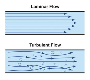
Figure 2: Laminar flow into microfluidic channels [3]
The laminar regime in microfluidics is used to mimic in vivo lymph and blood vessels for instance, which can provide not turbulent flows [4]. These conditions ensure the cells viability into micro-chips for a long-run experiments, such as cells migration or immune synapse study.
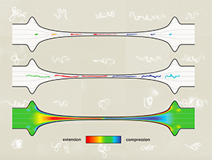
Such laminarity property is also used in the work of Anke Lindners lab (CS, ESPCI-PSL). They created a microfluidic device to characterise the dynamic behaviour of individual bio-particles such as DNA, actin filaments protein aggregates under homogeneous straining flow. The laminarity guides flow along a converging-diverging 100-50 µm large channel though which bio-molecules are compressed and elongated (Fig. 3) [5].
Figure 3: Protein elongation in a laminar through a microfluidic channel [5] - From CS lab.
[1] P. J. A. Kenis, R. F. Ismagilov and G. M. Whitesides, Microfabrication Inside Capillaries Using Multiphase Laminar Flow Patterning, Science, 285, 83-85 (1999)
[2] N. Convery, and N. Gadegaard, 30 Years of Microfluidics. Micro and Nano Engineering, 2, 7691 (2019)
[3] X. K. Li, Fundamentals of Fluid Mechanics By Joseph A. Schetz and Allen E. Fuhs (Eds.), John Wiley & Sons, New York, 1999, Journal of Non-Newtonian Fluid Mechanics, 91(23) (2000)
[4] F. Apoorva, A. M. Loiben, S. B. Shah, A. Purwada, L. Fontan, R. Goldstein, B. J. Kirby, A. M. Melnick, B. C. Cosgrove, and A. Singh, How Biophysical Forces Regulate Human B Cell Lymphomas. Cell Reports, 23(2), 499511 (2018)
[5] A. Liu, K. Zografos, J. Fidalgo, C. Duchêne, C. Quintard, T. Darnige, V. Filipe, S. Huille, O. du Roure, M. S. N. Oliveira, and A. Lindner, Optimised hyperbolic microchannels for the mechanical characterisation of bio-particles, Soft Matter, 43 (2020)
Capillary number: Viscous forces vs. Surface tension
The interfacial tension is a crucial feature of the liquid-liquid boundary. It is defined as the energy needed to modify the interface between two immiscible fluids. These forces are compared with dominant viscous forces in the laminar regime, in the Capillary number Ca is expressed as:
Ca = ν μ/ɣ
where ɣ is the interfacial tension, ν the fluid velocity, and μ its dynamic viscosity.
Lets take droplets generation as an example. The principle of droplet generation in microfluidic resides on the shearing of the dispersed medium by constant flow of the continuous phase. Several configurations of microfluidic chips exist to produce droplets. The most known and used are T-junction, co-flow, and flow-focusing designs (Fig. 4) [6]. In these three cases, two fluids meet at a junction point where the continuous phase shears the dispersed flow. This prompts a breakup of the dispersed phase. The size of droplets is tuned by the interfacial tension and the viscous forces of both fluids. In the case of oil-in-water droplets, water flows induce shear forces on oil phase: the greater water flow rate is, the higher shearing forces are. These parameters changes induce different modes such as dripping, jetting, and tip-streaming [7] and thus change the droplets size (Fig. 5). If the interfacial tension contribution, which tends to minimize the area of the water-oil interface, is higher than viscous forces, large droplets (> 15 μm) are formed by the dripping regime. By contrast, smaller droplets (between 10 and 15 μm) are formed when viscous forces are dominant with respect to interfacial tension, and tend to elongate the oil phase until its breakage. This regime is called jetting. The tip-streaming mode represents an extreme jetting regime where the thin and elongated oil flow produces droplets between 5 and 10 μm [8].
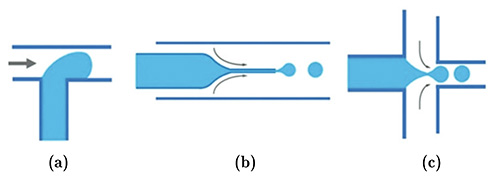
Figure 4: Three main microfluidic structures for droplet generation. (a) T-junction, (b) co-flow, and (c) flow focusing. The blueand the white media respectively represent the dispersed and continuous phases. The black arrows represent the flowdirection [6].
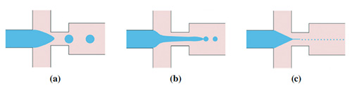
Figure 5: Three main modes of droplet generation. (a) Dripping, (b) jetting, and (c) tip streaming [7].
(i) Andrew Griffithss team (LBE, ESPCI-PSL) used this technology and created a droplet-based microfluidic chip to profile chromatin contribution to tumor cell heterogeneity, over thousands cells at single-cell resolution (Fig. 6A) [9].
(ii) A more technical example comes from Jérôme Bibettes lab (LCMD, ESPCI-PSL) which used a flow-focusing device to make droplets without any electronical device such as pressure controller or syringe pump. They smartly impose a negative flow with aspiration pipette. The resulting droplets sizes are homogeneous, and the dead volume is inexistent compared to other conventional methods (Fig. 6B) [10].
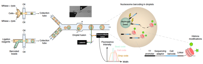
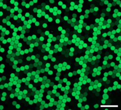
Figure 6: (A) Scheme of single-cell ChIP-seq chip work flow [9] - From LBE lab. (B) Epifluorescence microscopy of quantum dots-encapsulated droplets made with micropipette technique. Scale bar: 200 µm [10]. - From LCMD lab.
[6] W. Li, L. Zhang, X. Ge, B. Xu, W. Zhang, L. Qu, C. H. Choi, J. Xu, A. Zhang, H. Lee, and D. A. Weitz. Microfluidic fabrication of microparticles for biomedical applications. Chemical Society Reviews, 47 (15):56465683 (2018)
[7] A. S. Utada, L. Y. Chu, A. Fernandez-Nieves, D. R. Link, C. Holtze, and D. A. Weitz. Dripping, jetting, drops, and wetting: The magic of microfluidics. MRS Bulletin, 32(9):702708 (2007)
[8] N. M. Kovalchuk, E. Roumpea, E. Nowak, M. Chinaud, P. Angeli, and M. J.H. Simmons. Effect of surfactant on emulsification in microchannels. Chemical Engineering Science, 176:139152 (2018)
[9] K. Grosselin, A. Durand, J. Marsolier, A. Poitou,E. Marangoni, F. Nemati, A. Dahmani, S. Lameiras, F. Reyal, O. Frenoy, Y. Pousse, M. Reichen, A. Woolfe, C. Brenan, A. D. Griffiths, C. Vallot and A. Gérard, High-throughput single-cell ChIP-seq identifies heterogeneity of chromatin states in breast cancer,Nature Genetics, 51, 1066-1069 (2019)
[10] K Langer, N. Bremond, L. Boitard, J. Baudry, and J. Bibette Micropipette-powered droplet based microfluidics, Biomicrofluidics, 12, 044106 (2018)
Peclet Number: Diffusion vs. Mass transport
The dimensionless Peclet number compares the diffusion and convection of mass transport in microfluidic systems. It is often used in the context of mixing continuously flowing streams and is defined as:
Pe = L𝜌ν/D
where L is the chip length, 𝜌 is the density of the fluid, ν the velocity, and D the diffusion coefficient (m2.s-1).
The Peclet number can be extended as the ratio of characteristic time for diffusion (tdiff) to the characteristic convection time (τconv):
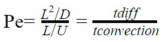
Where U is the fluid flow rate = 𝜌 ν.
For a microchannel with L = 100 μm (typical length of microfluidic channels), the Peclet number is 1000 for diffusivity (D) of 10-9 m2.s-1 (small molecules) and flow speed of 1 mm/s. If mixing occurs purely due to diffusion, the channel length must be 1000 times the channel height for two streams to mix in the channel, i.e. the channel length must be 10 cm. For larger biomolecules with a diffusivity of 10-11 m2/s (DNA) are to be mixed, the required channel length increases 100-fold to 10 m!
Clearly, in microchannels and at reasonably low flow rate, mixing ultimately occurs through diffusion process. For instance, microfluidic chips are created to mix two streams by diffusion that induce concentration gradient along the chip [11,12].
Figure 7: "Christmas tree" microfluidic mixer or gradient mixer [13]. - Image from EurekAlert (AAAS), Credits: Nichole Pamme.
[11] D. G. Rackus, I. H. Riedel-Kruse, and N. Pamme, Learning on a chip: Microfluidics for formal and informal science education, Biomicrofluidics 13, 041501 (2019)
[12] Y. Bao-Sheng, L. Ming, L. Bo-Ming, W. Shou-Yu, and Z. Wei-Guo. An integrated microfluidic device for screening the effective concentration of locally applied tacrolimus for peripheral nerve regeneration. Experimental and therapeutic medicine. 9, 154-158 (2015)
[13] N. Brandenberg, M. P. Lutolf, Chapter 27 - Employing Microfluidic Devices to Induce Concentration Gradients,Editor(s): A. Vishwakarma, J. M. Karp, Biology and Engineering of Stem Cell Niches, Academic Press, 2017, Pages 429-442.

 FR
FR EN
EN